





Before any lift begins, hydraulic checks confirm whether a crane can hold pressure, control load movement, and respond predictably under working conditions.
Why does a crane boom drift down under load? Common causes include internal cylinder leakage, worn control valves, inadequate hydraulic oil, trapped air, and pressure loss.
For operators, maintenance teams, fleet managers, and lifting supervisors, the priority is not merely finding visible leaks. It is verifying that hydraulic components can safely contain, direct, and sustain load-induced forces.
Start With the Hydraulic Conditions That Can Cause Boom Drift
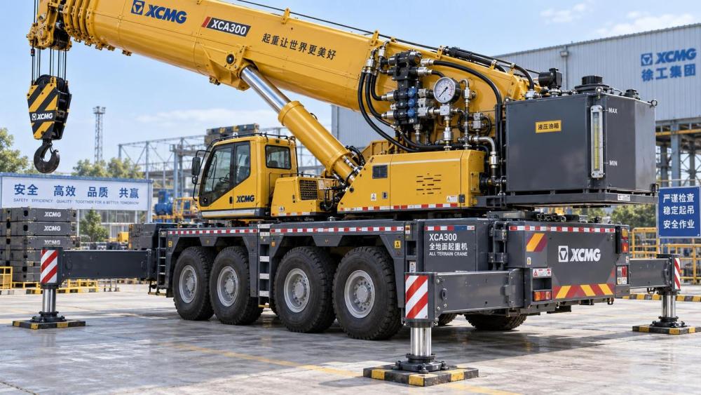
A boom that slowly lowers while the control lever is neutral is a serious warning sign. It indicates that hydraulic energy is escaping somewhere within the holding circuit.
External oil leakage is easy to notice, but internal leakage can be more dangerous because it may occur without visible fluid loss. Pressure bypasses inside components instead.
The most likely sources are boom lift cylinders, load-holding valves, directional control valves, pilot-operated check valves, and counterbalance valves designed to prevent uncontrolled descent.
A small amount of movement may occur as a crane structure settles under load. However, measurable, continuing boom descent requires investigation before lifting work proceeds.
Operators should record the boom angle, suspended load, hydraulic oil temperature, and time required for movement. These details help maintenance teams distinguish normal settling from a fault.
Drift under a heavy load usually becomes more visible when hydraulic oil warms. Lower oil viscosity can increase internal leakage through worn piston seals, valve spools, or damaged seats.
Never compensate for boom drift by repeatedly operating the controls or increasing engine speed. Those actions can hide the problem temporarily while increasing mechanical and safety risk.
The correct response is to isolate the crane, follow the manufacturer’s troubleshooting procedure, and confirm that every load-holding function performs within approved operating limits.
Check Hydraulic Oil Level, Condition, and Temperature Before Operation
Hydraulic oil is the crane’s power-transmission medium, lubricant, cooling fluid, and contamination carrier. Its level and condition directly affect boom control, pump performance, and component life.
Check the reservoir level using the manufacturer’s specified boom position and machine condition. A reading taken with cylinders extended may not represent the true available oil volume.
Low hydraulic fluid can introduce air into the suction line, causing pump cavitation, erratic boom movement, noise, reduced pressure, and accelerated wear of sensitive hydraulic components.
Inspect oil appearance through the sight glass or a clean sample container. Clear oil does not guarantee cleanliness, but cloudy, foamy, milky, darkened, or burnt-smelling oil needs attention.
Milky hydraulic oil often suggests water contamination. Water reduces lubricity, promotes corrosion, damages additive packages, and can cause sticking or corrosion in precision valve clearances.
Foam may indicate air ingress, incorrect oil level, incompatible fluid, poor return-line design, or degraded anti-foam additives. Air compressibility makes crane movements less controlled and repeatable.
Confirm that the oil grade matches the crane manufacturer’s requirement and the operating climate. Incorrect viscosity can create sluggish cold operation or excessive hot internal leakage.
Review operating temperature if the crane has recently worked continuously, lifted near capacity, or operated in hot weather. High temperature can reveal marginal pumps, valves, and seals.
Maintenance teams should treat repeated overheating as a reliability issue, not simply an operator inconvenience. It may point to relief-valve losses, restricted cooling, internal leakage, or excessive duty cycles.
Inspect for External Leaks, Hose Damage, and Connection Failures
Walk around the crane before startup and inspect the hydraulic system for wet fittings, damaged hoses, leaking cylinders, chafed lines, loose clamps, and oil accumulation around valve blocks.
Pay particular attention to boom lift cylinders, telescoping cylinders, outrigger circuits, swing motors, pump connections, and flexible hoses routed near pivot points or moving structural members.
Hydraulic hoses should not show exposed reinforcement, blistering, deep abrasion, crushing, cracking, twisting, kinks, or damaged protective sleeves. Any of these conditions can precede sudden failure.
Do not check for high-pressure leaks with bare hands. A pinhole hydraulic leak can inject fluid through skin, creating a medical emergency even when the visible oil stream seems small.
Use approved inspection methods, such as cardboard or a suitable shield, while maintaining safe distance from suspected leaks. Follow site procedures and wear required personal protective equipment.
Examine fittings for seepage, but avoid overtightening as a routine solution. Incorrect tightening can damage threads, distort sealing surfaces, or create cracks in adapters and valve housings.
Oil on walking surfaces also matters. A minor hydraulic leak can create slip hazards, contaminate work areas, mask a larger problem, and increase environmental cleanup costs.
Where possible, compare current hose condition with the crane’s maintenance records. Repeated failures in the same location may indicate routing errors, vibration, heat exposure, or unsuitable hose specification.
Verify Pump Performance and System Pressure Without Guesswork
The hydraulic pump must deliver adequate flow and pressure for the crane’s rated functions. Weak pump performance can cause slow operation, poor response, overheating, and unreliable load control.
Start by listening during normal function checks. Whining, rattling, growling, or fluctuating pump noise can indicate cavitation, aeration, suction restriction, worn internal parts, or inadequate oil supply.
Inspect suction hoses, strainers, reservoir breathers, and filters according to the manufacturer’s service instructions. Restrictions on the inlet side can damage a pump quickly.
Pressure verification should use calibrated gauges, approved test ports, and the crane manufacturer’s specified procedures. Improvised testing can expose personnel and equipment to dangerous stored energy.
Check standby pressure, relief pressure, pilot pressure, and function pressure only where applicable to the crane design. Compare readings with documented factory tolerances rather than assumptions.
A relief valve set too low may prevent normal lifting performance. A valve set too high can overload pumps, hoses, cylinders, structural components, and other parts of the hydraulic circuit.
Pressure that rises slowly or fluctuates during a controlled test may indicate pump wear, contaminated valves, internal leakage, air in the system, or a restriction downstream.
Fleet managers should retain pressure test results as trend data. A gradual decline can support planned repair before a marginal hydraulic system creates unscheduled downtime during a critical lift.
Test Cylinders for Internal Leakage and Rod Condition
Hydraulic cylinders convert fluid pressure into boom movement, extension, retraction, and outrigger support. Their seals, rods, barrels, pins, and mounting points require careful pre-operation inspection.
Inspect cylinder rods for scoring, corrosion, pitting, dents, or damaged chrome plating. Rod surface defects can rapidly destroy seals and permit external leakage or contamination entry.
Look for oil at gland areas, wiper seals, ports, and cylinder mounting points. External leakage must be corrected, but a dry cylinder can still leak internally.
Internal cylinder leakage occurs when pressurized oil passes across the piston seal from one chamber to another. The cylinder may then creep under load despite no visible oil loss.
A controlled drift test, performed only under approved conditions, can help identify whether the cylinder is bypassing internally. The procedure must follow manufacturer guidance and site lifting rules.
Do not place personnel beneath, beside, or within the potential movement path of a suspended load or boom during testing. Hydraulic troubleshooting must preserve exclusion-zone discipline.
Check cylinder pins, retaining hardware, bushings, and mounts as well. Excessive mechanical play can resemble hydraulic instability and can amplify boom movement during lifting operations.
When cylinder repair is required, use seals and components compatible with pressure, fluid type, temperature range, and crane duty cycle. Low-cost mismatched kits can create repeat failures.
Confirm That Load-Holding Valves Actually Hold the Load
Load-holding valves are central to crane safety because they prevent uncontrolled movement when a hose fails, a control valve leaks, or an operator releases the control.
Depending on the crane design, these functions may be provided by counterbalance valves, overcenter valves, pilot-operated check valves, hose burst valves, or integrated valve assemblies.
A counterbalance valve creates controlled resistance against an overrunning load. It helps prevent a boom from lowering too quickly when gravity tends to drive cylinder movement.
A pilot-operated check valve normally blocks return flow until pilot pressure deliberately opens it. If its poppet, seat, pilot piston, or spring is damaged, holding performance can degrade.
Contamination is a common reason for load-holding valve malfunction. Fine particles can prevent complete seating, score internal surfaces, or cause sticking that changes response characteristics.
Inspect the valve block and related hoses for damage, but do not disassemble safety-critical valves without correct procedures, clean conditions, technical data, and qualified personnel.
Symptoms of a faulty holding valve include gradual boom drift, inconsistent lowering speed, unstable movement after control release, or different behavior between cold and hot operating conditions.
Any suspected defect in a load-holding circuit should remove the crane from lifting service until inspection confirms the cause. This is a direct safety decision, not a productivity tradeoff.
Check Directional Valves, Pilot Controls, and Neutral Position
Directional control valves route hydraulic oil to crane functions. In neutral, they should hold or block flow as designed while allowing the correct pressure and return paths.
A worn spool, damaged seal, contaminated bore, weak centering spring, or incorrect adjustment can allow oil to bypass internally and contribute to boom movement under load.
Check that control levers, joysticks, pedals, and electronic pilot controls return cleanly to neutral. Binding linkages or faulty sensors may command unintended valve movement.
Modern cranes may use electrohydraulic proportional valves with electronic control modules. Diagnostic fault codes, sensor readings, and calibration status should be reviewed before complex mechanical repairs begin.
Operators should report delayed response, jerky movement, creeping functions, or controls that feel different from normal. These operational observations are valuable diagnostic evidence, not minor complaints.
Inspect pilot lines for leakage, crushing, loose fittings, and contamination. Low or unstable pilot pressure can prevent valves from shifting correctly or fully returning to their holding position.
Where the crane uses remote controls, verify signal integrity, battery condition, emergency-stop function, and communication status. A hydraulic system cannot be considered safe if command control is unreliable.
Inspect Filters, Breathers, and Contamination-Control Practices
Hydraulic contamination is one of the leading causes of premature pump, valve, seal, and cylinder failure. Crane hydraulic checks should therefore include the system’s contamination-control components.
Review filter restriction indicators and maintenance intervals. A clogged filter can restrict flow, trigger bypass operation, or reduce protection precisely when the system needs clean oil most.
Replacing a filter without investigating its debris can miss the underlying failure. Metal particles, rubber fragments, sludge, or unusual material may identify a deteriorating component.
Reservoir breathers deserve equal attention because they control airborne contamination and moisture entry. A damaged or saturated breather can undermine otherwise disciplined fluid maintenance practices.
Use clean, dedicated transfer equipment when adding oil. Dirty funnels, unsealed containers, and mixed lubricants introduce contaminants that can damage high-clearance hydraulic valves and pumps.
For high-utilization crane fleets, oil analysis can support condition-based maintenance. Particle count, water content, viscosity, oxidation, and wear metals provide evidence beyond visual inspection.
Cleanliness targets should reflect crane design, component sensitivity, operating environment, and manufacturer recommendations. A generic filtration practice may be insufficient for modern proportional hydraulic systems.
Test Critical Crane Functions Before the First Lift
After visual inspection and approved hydraulic checks, function-test the crane without a suspended load whenever practical. Confirm smooth, predictable movement through the required operating range.
Test boom raise, lower, telescope, swing, hoist-related hydraulic functions, outriggers, and any auxiliary circuits used for the planned work. Watch for hesitation, surging, noise, and drift.
Outrigger checks are especially important because crane stability depends on firm setup. Hydraulic outrigger cylinders must extend, hold, and retract evenly without visible leakage or unexpected settlement.
Verify that interlocks, load moment indicators, alarms, pressure warnings, and emergency functions operate correctly. These systems complement hydraulic integrity but do not replace proper inspections.
Function tests should occur in a controlled area with clear communication, exclusion zones, and adequate ground conditions. The test itself must never introduce avoidable lifting risk.
If a fault appears intermittently, document the conditions instead of assuming it has disappeared. Note oil temperature, engine speed, load condition, function selected, and any warning indicators.
Recurring defects should be escalated through a formal maintenance process. Repeated operator observations often reveal developing hydraulic failures before they become reportable incidents or major repairs.
Use a Pre-Operation Checklist That Supports Better Decisions
An effective crane hydraulic checklist should be short enough for consistent use but detailed enough to identify conditions that could compromise lifting safety or equipment reliability.
Include hydraulic oil level, fluid appearance, visible leaks, hose condition, cylinder condition, filter indicators, abnormal sounds, control response, holding performance, and warning-system status.
For planned heavy lifts, add documented pressure tests, load-holding verification, recent maintenance history, component replacement records, and confirmation that the crane configuration matches the lift plan.
Maintenance supervisors should define clear removal-from-service criteria. Examples include active high-pressure leaks, boom drift beyond specification, damaged hoses, abnormal pump noise, or failed load-holding tests.
Procurement teams also benefit from this discipline. Selecting quality pumps, cylinders, seals, filters, hoses, and valves reduces lifecycle cost when components are matched to the actual duty cycle.
Cheap replacement parts can increase downtime when material compatibility, pressure rating, contamination tolerance, and dimensional accuracy are not controlled. Traceable industrial components protect availability and safety.
Good records turn routine checks into a reliability program. They help identify recurring failure modes, improve spare-parts planning, justify preventive maintenance, and reduce emergency repair costs.
Conclusion: Treat Boom Drift as a Hydraulic Safety Signal
Before crane operation, hydraulic checks must confirm that the system has clean oil, adequate pressure, intact hoses, healthy cylinders, responsive controls, and reliable load-holding capability.
Why does a crane boom drift down under load? In most cases, oil is bypassing internally through a cylinder, holding valve, directional valve, or another pressure-retaining component.
The practical conclusion is straightforward: do not normalize creeping, inconsistent control, overheating, or pressure loss. These symptoms require documented inspection and qualified corrective action before lifting resumes.
By combining disciplined pre-operation checks with component-quality standards, condition monitoring, and maintenance records, crane owners can reduce lifting risk, avoid downtime, and extend hydraulic system life.
Related News
- 00
0000-00
How to assess a mechanical seal solutions supplier’s quality control - 00
0000-00
How to use chain wear analysis to prevent mining conveyor failures - 00
0000-00
How to select PU timing belts for automation with high positioning accuracy - 00
0000-00
How to size power transmission systems for steel mill loads - 00
0000-00
How to select heavy duty metallurgy belts for high-temperature loads
Weekly Insights
Stay ahead with our curated technology reports delivered every Monday.