





Turbine operating speed influences bearing heat generation, lubrication requirements, vibration behavior, and service life. Selecting a bearing therefore requires more than checking its maximum speed rating.
Shaft diameter, load, operating temperature, lubricant delivery, and rotor dynamics all shape the final choice. The right bearing must perform across the complete operating cycle.
For technical evaluators, the central question is whether the proposed bearing system maintains adequate lubrication, stability, and life at every relevant speed and load.
Why a bearing’s maximum speed rating is only a starting point
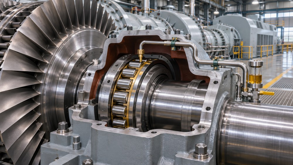
A catalog speed rating provides a useful screening value under stated conditions. It does not guarantee that a bearing will operate safely in a particular turbine.
Manufacturers may distinguish between reference speed, associated with thermal considerations, and limiting speed, associated with mechanical or functional constraints. Definitions and calculation methods vary by supplier.
Actual capability depends on factors including bearing geometry, cage design, load, lubricant, cooling, fits, and mounting arrangement. A rating without these conditions has limited decision value.
For example, a bearing rated above the turbine’s nominal speed may still overheat if oil flow is inadequate or preload increases excessively as temperatures change.
Conversely, a catalog value does not always represent an absolute ceiling. A manufacturer may support higher speeds with an engineered arrangement and application-specific validation.
Begin with the entire speed profile: startup, acceleration, rated operation, part-load operation, transient overspeed, and shutdown. Record duration and frequency, not just peak rpm.
Also identify whether the bearing supports the turbine rotor directly or a gearbox shaft. Their speeds, loads, and failure mechanisms can differ substantially.
How should shaft diameter change the speed assessment?
Rotational speed in rpm is only part of the story. A larger bearing experiences greater surface speed at the same rpm, affecting friction and lubrication demands.
Engineers often use the speed factor ndm, calculated as rotational speed multiplied by bearing mean diameter. Mean diameter is approximately the average of bore and outside diameter.
For a bearing with a 100 mm mean diameter running at 20,000 rpm, the resulting speed factor is 2 million mm·rpm.
At the same speed, a bearing with a 200 mm mean diameter reaches 4 million mm·rpm. The larger bearing may require a different design and lubrication strategy.
Use this calculation to compare operating severity and screen supplier recommendations. It is not a universal acceptance limit: permissible values depend on bearing type and operating conditions.
Confirm whether the supplier uses mean diameter, bore diameter, or another measure in its speed factor. Comparing values calculated on different bases can mislead.
When shaft diameter is dictated by rotor strength or stiffness, the bearing choice must accommodate that geometry. Reducing bearing size may compromise the wider rotor design.
Which bearing types fit different turbine speed and load demands?
Precision bearing systems for turbines include rolling-element, hydrodynamic, and other engineered bearing arrangements. The appropriate choice depends on rotor architecture as well as operating speed.
Angular contact ball bearings can support combined radial and axial loads and are used in some high-speed machinery. Contact angle, preload, cage, and lubrication govern suitability.
Ball bearings generally offer lower rolling resistance than comparably sized roller bearings, but their load capacity and stiffness must be checked for the specific application.
Cylindrical roller bearings can provide substantial radial load capacity and stiffness. Their high-speed suitability depends on internal design, cage behavior, lubrication, and axial locating arrangements.
Duplex angular contact arrangements can locate a shaft axially in both directions. Evaluate their preload, thermal response, and load sharing rather than selecting solely by bearing class.
Hydrodynamic journal bearings support the shaft on a lubricant film during suitable operating conditions. They are common in many large industrial turbines and high-speed rotor systems.
Tilting-pad journal bearings can provide favorable rotordynamic characteristics in demanding applications. Their performance depends on pad geometry, oil supply, load, clearance, and system dynamics.
Hydrodynamic thrust bearings manage axial load through an oil film. Startup, shutdown, and low-speed operation deserve attention because a full supporting film may not yet exist.
Magnetic bearings offer active rotor support without normal mechanical contact, but require controls, power, sensors, and backup bearings. Assess the complete system and failure response.
No bearing category is inherently best for every turbine. Compare viable arrangements against the actual duty cycle, installation constraints, reliability targets, and available support systems.
How do speed and temperature affect lubrication?
As speed rises, friction and lubricant churning can increase heat generation. Temperature then changes lubricant viscosity, bearing clearances, component dimensions, and potentially the load distribution.
The relationship is not always linear. Oil quantity, drag, cooling, bearing design, and operating load can change how heat generation varies across the speed range.
For rolling bearings, the lubricant must provide an adequate film between contacting surfaces while controlling friction. Excessive oil can create churning losses and raise temperature.
Insufficient oil can reduce film thickness, increase wear, and shorten fatigue life. At high speeds, lubricant must also reach critical contacts despite airflow and centrifugal effects.
Oil-air, oil-mist, and oil-jet systems are possible approaches for certain rolling-bearing applications. Their suitability depends on bearing design, environmental requirements, and supplier recommendations.
For oil-jet lubrication, evaluate jet placement, velocity, flow rate, filtration, and drainage. A nominal pump capacity alone does not prove effective delivery inside the bearing.
Hydrodynamic bearings require an appropriate oil supply to establish and maintain the designed film and remove heat. Check inlet temperature, pressure, flow, and return conditions.
Viscosity must be assessed at operating temperature, not only at ambient conditions. Cold starts also matter because excessive viscosity can affect flow and starting behavior.
Ask suppliers for predicted bearing temperatures, oil outlet temperatures, and minimum film thickness across representative operating points. Compare predictions with the proposed monitoring limits.
Review abnormal conditions too: loss of cooling, reduced oil pressure, contaminated lubricant, and shutdown after a trip. Define protective actions and allowable response times.
Can the bearing arrangement control vibration across the speed range?
A turbine bearing is part of a rotor-bearing-support system. Its stiffness and damping interact with shaft flexibility, housing structure, seals, couplings, and operating conditions.
As the rotor accelerates, it may pass through critical speeds where vibration response increases. The bearing arrangement must support acceptable behavior during passage and continuous operation.
A rotor dynamics study should consider the intended speed range, expected unbalance, support properties, and relevant operating temperatures. It should also assess credible variations in those inputs.
Hydrodynamic bearing coefficients can change with speed, load, temperature, and clearance. Ask whether the analysis uses coefficients appropriate to each operating condition.
For rolling bearings, support stiffness depends on bearing configuration, internal clearance or preload, load, fits, and surrounding structure. Assuming a rigid housing can distort predictions.
Evaluate vibration at both bearing locations and other critical points, using the measurement conventions and acceptance criteria agreed for the equipment. Trends matter alongside absolute limits.
Stability deserves separate attention from critical-speed separation. Some rotor systems can develop self-excited vibration even when their steady operating speed appears adequately separated from a critical speed.
If magnetic bearings are proposed, request evidence covering control stability, power loss, sensor faults, backup bearing loads, and the expected number of permissible rotor drops.
What load, precision, and life evidence should evaluators request?
Speed does not replace load analysis. Document radial and axial forces, their direction, transient peaks, and how load changes during startup, operation, and shutdown.
Axial thrust can vary with pressure, flow, seal condition, and operating mode. For opposed bearing arrangements, determine how thrust reversals affect load sharing and preload.
For rolling bearings, request a life calculation using the actual duty cycle, lubrication conditions, contamination assumptions, and manufacturer methodology. Identify which failure modes the calculation excludes.
Calculated fatigue life does not by itself predict failures caused by poor lubrication, electrical damage, corrosion, cage instability, improper installation, or rotor rubs.
For fluid-film bearings, assess minimum film thickness, metal temperatures, oil flow, and stability margins. Conventional rolling-bearing fatigue life calculations do not describe their performance.
Precision classes describe specified manufacturing tolerances and running accuracy. A higher class can support demanding rotor requirements, but it does not automatically ensure longer service life.
Specify the tolerances that matter to the assembly, including bore and outside diameter, runout, and mounting surfaces. Align the selected standard and class with supplier documentation.
Confirm shaft and housing fits at operating temperature. Thermal expansion and interference fits can alter internal clearance or preload, changing friction, stiffness, and bearing life.
For demanding applications, ask how the supplier controls material quality, heat treatment, surface finish, cage integrity, cleanliness, and traceability. Match inspection requirements to documented risks.
How can procurement teams compare supplier proposals?
Issue each supplier the same application envelope, including shaft geometry, operating speeds, loads, temperatures, lubricant properties, cooling capacity, and expected starts per year.
Request a system-level proposal that identifies the bearing arrangement, calculated operating conditions, lubrication requirements, instrumentation, installation tolerances, and limitations of the analysis.
Compare assumptions before comparing results. Two calculated lives or temperature predictions are not directly equivalent if suppliers use different loads, contamination levels, or oil temperatures.
Ask for evidence from comparable applications or relevant tests, including operating speed, bearing size, lubricant delivery, duration, and observed temperatures or vibration where available.
Review qualification plans for overspeed, startup, shutdown, and foreseeable trips. Confirm whether the proposed test represents the assembled system or only an individual bearing.
Include maintenance requirements in the comparison: oil condition checks, filter replacement, sensor calibration, inspection intervals, spare availability, and the skills needed for installation.
Total ownership cost should account for auxiliary equipment and downtime exposure as well as purchase price. A lower bearing price may require more expensive cooling or maintenance.
Before acceptance, agree on measurable limits for temperature, vibration, oil supply, and operating conditions. Assign responsibility for investigating deviations during commissioning and service.
Making the final selection
The strongest selection demonstrates that the bearing arrangement, lubrication system, and rotor dynamics work together throughout the turbine’s operating envelope, including transient and abnormal conditions.
Use speed ratings and speed factors to identify candidates, then validate them against loads, thermal behavior, clearances, vibration, and application-specific supplier evidence.
For technical evaluators, a defensible decision is one whose assumptions, operating limits, monitoring plan, and maintenance consequences are clear before the turbine enters service.
Want to dive deeper into these market dynamics, or need data-driven support for your next business move? Drop a line below and let the analysts at PCTS provide customized insights.
We respect your privacy. Your information is strictly confidential.
Related News
- 00
0000-00
How to assess a chain and belt drive manufacturer's quality control - 00
0000-00
How intelligent condition monitoring detects conveyor bearing faults - 00
0000-00
How misalignment affects belt drive components - 00
0000-00
Trelleborg Sealing Solutions Uses AI to Optimize Rotary Shaft Seal Design - 00
0000-00
How turbine operating speed affects precision bearing selection
Weekly Insights
Stay ahead with our curated technology reports delivered every Monday.