





A belt that fails shortly after replacement can leave a maintenance team facing an uncomfortable question: was the belt defective, or was the underlying problem left in place? Misalignment is a common reason that new belt drive components inherit the same wear pattern as the old ones. It can increase belt edge wear, vibration and noise while placing additional loads on pulleys, shafts and bearings.
For after-sales maintenance personnel, the challenge is not simply to make two pulleys look straight. It is to identify how the drive is misaligned, distinguish alignment damage from tension or component defects, and restore the drive to the equipment manufacturer’s requirements. A careful inspection can prevent another replacement from becoming another repeat failure.
What misalignment means in a belt drive
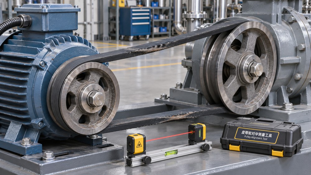
A belt drive is aligned when the pulleys or sheaves are positioned so the belt runs in the intended plane and engages them correctly. The details depend on the drive: a V-belt runs in pulley grooves, a synchronous belt engages toothed pulleys, and a flat belt relies on the pulley surfaces and tracking characteristics specified for the system.
Two basic alignment errors often occur together:
- Parallel offset: The shafts are parallel, but the pulley grooves or working faces do not sit in the same plane. The belt must angle sideways as it travels between pulleys.
- Angular misalignment: The shaft centerlines are not parallel. One pulley is tilted relative to the other, either horizontally or vertically, so the belt approaches and leaves the pulleys at an angle.
A motor can be offset and tilted at the same time. Correcting only one condition may make the drive look better while leaving enough error to continue damaging the belt. An apparently good alignment can also change under load if a motor base moves, a frame flexes or a bearing develops excessive play.
How misalignment affects belt drive components
Belts: edge wear, heat and unstable tracking
A belt is designed to transmit power while following a defined path. When the pulleys are misaligned, the belt can enter a groove or tooth engagement at an angle instead of seating evenly. That adds rubbing and side loading, concentrating wear where the belt contacts the pulley.
On a V-belt, inspect for uneven wear on the sidewalls, frayed edges, glazing or damaged belt sections. On a synchronous belt, edge fraying, tooth damage or persistent contact with a pulley flange can point toward a tracking problem. A flat belt may drift toward one side, although its tracking behavior also depends on pulley geometry and the system design.
Heat and wear are not proof of misalignment by themselves. Over-tensioning, under-tensioning, contamination, incorrect pulley profiles and damaged pulleys can produce similar symptoms. The useful clue is the combination of the wear pattern, the alignment measurement and the operating history.
Pulleys and sheaves: uneven contact becomes a wear pattern
Misalignment can wear pulley grooves or toothed surfaces unevenly. A worn V-belt groove may no longer support the belt correctly, while a damaged synchronous pulley can compromise tooth engagement. In either case, fitting a new belt to a damaged pulley may shorten the new belt’s life even after alignment has been corrected.
Check pulley faces, grooves, teeth and flanges for scoring, burrs, cracks and abnormal wear. Use the appropriate profile gauge where recommended by the manufacturer. Also look for wobble or runout, which may result from a bent shaft, poor mounting, a damaged hub or pulley defects. Alignment adjustment alone will not repair those conditions.
Bearings, shafts and supporting structures
Misalignment changes how belt forces are applied to the pulleys and shafts. Depending on the drive arrangement and tension, the resulting uneven or additional loading can contribute to bearing wear, shaft deflection and vibration. A bearing that repeatedly runs hot or fails near a belt drive deserves an alignment check, but it should also be assessed for lubrication problems, contamination, fit and other loading issues.
The support structure matters too. A loose motor mount, cracked base or soft foot can allow the machine to move after the alignment is set. If the base cannot hold its position, careful pulley alignment during a shutdown may not represent the drive’s condition in service.
Read the symptoms before making adjustments
Maintenance teams often arrive after the obvious event: a snapped belt, a noisy drive or a guard full of rubber dust. Before dismantling anything, record what can still be observed safely. Photographs of belt edges, pulley contact areas and motor positions can be useful when comparing failures across service visits.
These are diagnostic leads, not a fault-code chart. For example, a squealing V-belt may be slipping because it is under-tensioned; tightening it without checking alignment and pulley condition can replace one problem with excessive bearing load.
A practical inspection and alignment workflow
The following sequence is intended as a field framework, not a substitute for the machine and belt manufacturers’ instructions. Record the as-found condition before adjustment so the final measurements can be compared with it.
- Make the equipment safe. Shut down, isolate and lock out all relevant energy sources. Verify isolation and secure any components that could move under stored energy. Remove guards only when it is safe to do so.
- Inspect the mounting and drive components. Look for loose fasteners, damaged bases, soft foot, worn bearings, pulley wobble and damaged grooves or teeth. Correct defects that would prevent a stable alignment.
- Check pulley position. Confirm that each pulley is properly seated and secured on its shaft. Do not assume the outside faces of two pulleys are equivalent reference surfaces; pulley designs and face offsets may differ.
- Measure offset and angular error. Use a suitable straightedge, string or pulley alignment tool according to its instructions. A laser pulley alignment tool can make offset and angular errors easier to see, but the reading is only meaningful if the correct pulley reference surfaces and offsets are used.
- Adjust the machine or pulley position. Move the adjustable machine horizontally as needed, and use suitable shims for vertical corrections. Where the design permits pulley repositioning on the shaft, follow the manufacturer’s mounting and locking procedure.
- Set belt tension and recheck alignment. Apply the tension specified for the belt and drive using the recommended measurement method. Tightening mounting bolts and tensioning the belt can shift the machine, so verify alignment again after both operations.
- Restore and observe. Refit guards, remove isolation in accordance with site procedure and run the equipment under appropriate conditions. From a safe position, listen and observe for abnormal noise, vibration or tracking. Stop and investigate if the behavior is not normal.
For multi-groove V-belt drives, inspect the complete belt set and follow the manufacturer’s guidance on replacement. Mixing belts with different wear or length characteristics can lead to unequal load sharing. Never force a belt over a pulley flange or roll it into a groove with a tool; adjust the center distance to install it without damage.
Alignment tolerances: which standard should you use?
There is no single numerical limit that should be applied automatically to every belt drive. Acceptable misalignment depends on the belt type, pulley geometry, center distance, operating conditions and manufacturer’s design requirements. Synchronous, V-belt and flat-belt systems can have different sensitivity to tracking and side loading.
Use the equipment manufacturer’s specifications first, together with the belt and pulley suppliers’ installation instructions. If an applicable industry standard is referenced in the equipment documentation, check that it covers the drive and measurement method in question. Do not substitute a shaft-coupling alignment tolerance for a pulley alignment tolerance without confirming that it is appropriate.
Also note how a limit is expressed. An angular value, a gap measured at a given distance and a pulley offset are not interchangeable without the relevant geometry. Record the measurement method, reference surfaces and final readings; “aligned” alone is difficult for the next technician to verify.
When a correctly aligned drive still fails
If measurements are acceptable at rest but wear returns, investigate what changes during operation. Heat can alter machine position, a loaded structure can deflect, and a motor can shift on a loose base. Check whether the drive’s operating conditions differ from those assumed during installation, using the equipment manufacturer’s guidance and site safety procedures.
Repeated failure can also come from a cause outside alignment. An incorrect belt profile, worn sheave grooves, excessive tension, insufficient tension, oil contamination or a seized driven component can all damage a correctly aligned drive. On synchronous systems, tooth or flange damage should prompt a check of pulley condition, installation and loading rather than an alignment adjustment alone.
Close the service record with the belt and pulley condition, alignment readings, tension method, replaced parts and any unresolved observations. At the next inspection, those details provide a baseline: the team can see whether belt drive components are wearing evenly, whether settings have moved and whether the repair addressed the cause rather than just the symptom.
Want to dive deeper into these market dynamics, or need data-driven support for your next business move? Drop a line below and let the analysts at PCTS provide customized insights.
We respect your privacy. Your information is strictly confidential.
Related News
- 00
0000-00
How to assess a chain and belt drive manufacturer's quality control - 00
0000-00
How intelligent condition monitoring detects conveyor bearing faults - 00
0000-00
How misalignment affects belt drive components - 00
0000-00
Trelleborg Sealing Solutions Uses AI to Optimize Rotary Shaft Seal Design - 00
0000-00
How turbine operating speed affects precision bearing selection
Weekly Insights
Stay ahead with our curated technology reports delivered every Monday.