





Choosing a fluid power dynamics supplier involves more than comparing pumps, valves and prices. The decisive question is whether its engineering team can translate operating requirements into a reliable system.
Technical evaluators should examine load calculations, component selection, control stability, energy efficiency, safety and validation. Requesting design evidence early helps distinguish genuine system capability from product selection expertise.
What Evidence Shows a Supplier Can Design the Whole System?
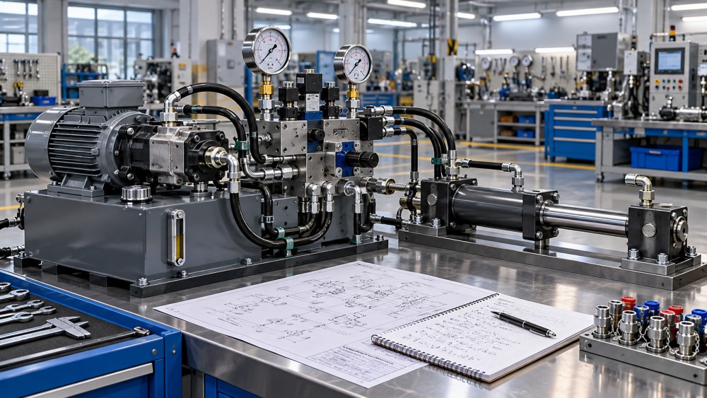
A capable supplier should connect the application requirements to calculations, a schematic, component specifications, control settings and a verification plan. Each decision should be traceable.
Ask for an anonymized design package from a comparable application. Look for operating cases, assumptions, calculation revisions, test results and evidence that problems were resolved.
A polished component catalog is not a substitute for this package. Neither is a successful project reference unless the supplier explains its own engineering responsibilities.
Clarify whether the supplier performs calculations and commissioning internally, relies on component manufacturers, or subcontracts specialist work. External expertise can be valuable when responsibilities and deliverables are explicit.
Finally, ask the proposed engineering team to explain a trade-off in its design. Strong answers identify constraints, alternatives, expected consequences and how uncertainty will be checked.
Can the Supplier Define Loads and Operating Conditions?
System sizing begins with more than nominal force and speed. The supplier should establish a duty cycle covering peak loads, acceleration, dwell periods, simultaneous movements and expected variation.
For a hydraulic cylinder, request calculations for force, pressure, flow and movement time in both directions. Rod area changes effective force and flow during retraction.
For rotating loads, ask how the team estimates torque, speed, starting behavior and inertia. It should consider load reversals, shock loading and pressure losses across the circuit.
For pneumatic applications, check that force calculations use realistic working pressure at the actuator, not simply compressor discharge pressure. Friction, cushioning and pressure fluctuations also affect performance.
Review environmental assumptions: ambient temperature, fluid temperature, humidity, contamination, washdown, vibration and available cooling. A design suitable for a clean factory may fail in outdoor service.
Ask the supplier to identify missing information and propose measurements or conservative assumptions. Unquestioned inputs can make accurate calculations produce an unsuitable design.
How Does the Supplier Size Components and Manage Pressure Loss?
Request a schematic and a component selection schedule showing rated pressure, flow, speed, temperature range and compatibility. Ratings should cover normal operation and credible transient conditions.
Examine the pump or compressor selection against the actual duty cycle. A unit sized only for a brief peak may waste energy and complicate thermal management.
Ask for pressure-loss calculations through hoses, pipes, filters, fittings and valves at relevant flow rates. Excessive losses reduce available actuator force and generate heat.
Check how the supplier selects line sizes and explains trade-offs between pressure drop, fluid velocity, space and cost. Suction conditions deserve particular attention in hydraulic systems.
A hydraulic pump must receive adequate inlet pressure under worst-case fluid viscosity and temperature. Ask how the design avoids cavitation, including consideration of elevation and filter restrictions.
For pneumatics, assess air preparation, distribution capacity and pressure stability at the point of use. Undersized piping or excessive leakage can undermine otherwise correct actuator sizing.
Seals, hoses and filtration should match the medium and operating conditions. Ask for documented compatibility with the specified fluid, temperature range and expected contaminants.
Can the Design Control Motion Without Instability?
Motion quality depends on the interaction of the actuator, valve, load, fluid and controller. Evaluators should ask for performance targets, not just a list of components.
Specify acceptable position error, speed variation, settling time and overshoot where relevant. The supplier should explain how these targets will be measured under representative loads.
For hydraulic axes, ask how hose compliance, trapped air, valve response and load inertia affect stability. A design that works unloaded may oscillate under production conditions.
For pneumatic motion, compressibility makes precise positioning and consistent speed more challenging. Ask how the supplier manages pressure variation, cushioning and changes in payload.
Where dynamics are critical, request an appropriate model or simulation and its assumptions. Confirm how the model will be checked against commissioning measurements.
Discuss control ownership across mechanical, fluid power and automation teams. Valve selection, sensor placement, controller tuning and machine logic must be coordinated rather than designed independently.
How Will the Supplier Limit Energy Use and Heat?
Ask for estimated power consumption across the duty cycle, including standby periods. Compare alternatives using the same operating assumptions, production hours and energy price.
In hydraulics, the supplier should explain losses from throttling, pressure drop, leakage and pressure relief. These losses affect both operating cost and fluid temperature.
Request a heat balance covering heat generation, reservoir dissipation and cooling capacity. The design should remain within component and fluid limits at the expected ambient temperature.
For pneumatics, review compressed-air consumption, operating pressure, leakage allowances and opportunities to isolate idle equipment. Compressor system conditions should be included in the assessment.
Efficiency recommendations should not compromise response, safety or reliability. Ask the supplier to quantify expected savings and identify assumptions that could materially change the result.
Are Safety and Standards Built Into the Design?
Ask how the supplier contributes to the machine risk assessment and how its circuit addresses identified hazards. Responsibility for overall machine safety must be clearly assigned.
Review protection against overpressure, uncontrolled movement, stored energy and unexpected restart. Consider power loss, hose failure, maintenance isolation and the consequences of component failure.
Where a suspended or vertical load is present, request an explanation of load-holding arrangements and failure behavior. Confirm that the proposed solution suits the actual load and application.
Check relevant standards and local regulatory requirements for the machine and destination market. ISO 4413 covers hydraulic systems, while ISO 4414 covers pneumatic systems and their components.
These standards do not replace an application-specific risk assessment. Ask which requirements apply, what evidence will be supplied and who verifies the complete machine.
For safety-related controls, establish required functions, validation responsibilities and applicable control-system standards with the machine builder. Avoid assuming a component rating proves system-level safety.
What Testing Proves the System Meets Its Requirements?
Request a verification plan before placing the order. It should connect each critical requirement to a test method, acceptance limit, operating condition and responsible party.
Factory testing may cover pressure settings, leakage, flow, actuator speed, controls and protective functions. Define which results will be recorded and witnessed by the buyer.
Where practical, test representative loads and duty cycles rather than relying exclusively on unloaded operation. Document any conditions that cannot be reproduced before installation.
For dynamic performance, specify sensor locations, sampling methods and pass criteria. A statement that motion is “smooth” is less useful than measured response against agreed limits.
Agree on site acceptance tests for installation-dependent behavior, including integration with machine controls and available utilities. Assign responsibility for tuning, troubleshooting and retesting after changes.
Ask how the supplier handles failed tests and design revisions. The process should include root-cause investigation, corrective action and updated documentation before final acceptance.
Will the Design Be Maintainable Over Its Lifecycle?
A technically sound system should also be serviceable. Review access to filters, valves, test points, cylinders and electrical connections before layouts and enclosure dimensions are frozen.
Ask for contamination-control targets and practical maintenance instructions. Hydraulic filtration strategy should reflect component sensitivity, operating conditions and the ability to monitor filter condition.
For pneumatic systems, examine condensate management, filter maintenance and leak detection. Neglected air preparation can shorten component life and create inconsistent machine performance.
Request a spare-parts list identifying critical items, lead times and approved alternatives. Proprietary components are not automatically unacceptable, but availability and replacement risk need scrutiny.
Confirm delivery of as-built schematics, bills of materials, settings, manuals and software backups where applicable. Documentation should reflect commissioning changes, not only the original proposal.
Compare lifecycle costs using acquisition, energy, maintenance, spares and downtime assumptions. Treat uncertain figures as scenarios rather than presenting estimated savings as guaranteed outcomes.
How Should You Compare Competing Suppliers?
Use the same application brief and operating cases for every bidder. Ask each supplier to identify exclusions, uncertainties and information needed to complete its design.
Score technical responses against weighted criteria suited to the project. For a motion-critical machine, control performance and validation may matter more than initial equipment price.
Consider an assessment with 25 points for requirements and calculations, 20 for circuit and component selection, and 20 for controls and dynamic performance.
Allocate another 15 points to safety, 10 to testing and 10 to maintainability. Adjust the weights for project risk and define the evidence needed for each score.
Set mandatory requirements separately from the weighted score. A supplier should not compensate for an unacceptable safety or validation gap with a low price.
During technical review, present a changed load, duty cycle or ambient condition. Ask the team to explain which calculations, components and acceptance tests would need revision.
Watch for unsupported claims, unexplained margins, missing failure scenarios and vague test commitments. These are reasons to seek clarification, not automatic proof that a design is defective.
Conclusion: Select on Traceable Engineering Evidence
The strongest fluid power dynamics supplier can show how requirements become calculations, circuit decisions, safeguards and measurable acceptance criteria. Its engineers can also explain uncertainty and trade-offs.
Before selection, compare complete design evidence, confirm responsibility boundaries and agree on testing. That gives procurement and engineering teams a firmer basis for managing performance and lifecycle risk.
Want to dive deeper into these market dynamics, or need data-driven support for your next business move? Drop a line below and let the analysts at PCTS provide customized insights.
We respect your privacy. Your information is strictly confidential.
Related News
- 00
0000-00
How to assess a chain and belt drive manufacturer's quality control - 00
0000-00
How intelligent condition monitoring detects conveyor bearing faults - 00
0000-00
How misalignment affects belt drive components - 00
0000-00
Trelleborg Sealing Solutions Uses AI to Optimize Rotary Shaft Seal Design - 00
0000-00
How turbine operating speed affects precision bearing selection
Weekly Insights
Stay ahead with our curated technology reports delivered every Monday.