





Why do hydraulic systems matter so much in industrial equipment?
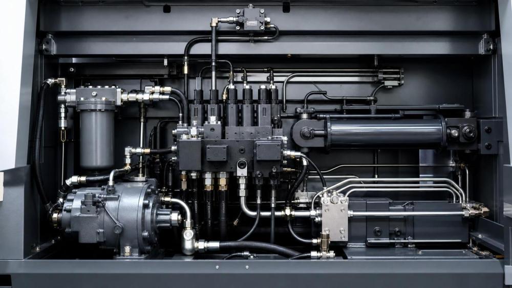
Hydraulic systems turn fluid pressure into usable force, motion, and lifting power. That simple principle supports presses, excavators, injection machines, lifts, machine tools, and many automated production lines.
In practical terms, hydraulic systems matter because they deliver high power density. A compact assembly can move heavy loads with stable control, even when space is limited.
They also make precise movement possible. Speed, direction, and force can be adjusted with valves, sensors, and pressure settings, which is why fluid power remains central in heavy and precision applications.
This is also where evaluation becomes important. A hydraulic circuit may look simple on paper, yet real performance depends on pump design, sealing quality, contamination control, and thermal stability.
Across industrial component analysis, hydraulic systems rarely stand alone. They interact with bearings, couplings, seals, motors, filters, and monitoring devices, so reliability must be judged as a system, not a single part.
That broader view is increasingly reflected in professional intelligence platforms such as PCTS, where fluid power is evaluated alongside transmission parts, sealing materials, wear behavior, and maintenance economics.
What are the basic components inside hydraulic systems?
Most hydraulic systems use a familiar architecture. Understanding the role of each component makes fault analysis and supplier comparison much easier.
The power source starts with the pump
The hydraulic pump converts mechanical input into fluid flow. It does not create pressure by itself. Pressure appears when flow meets resistance inside the circuit.
Common pump types include gear, vane, and piston designs. Piston pumps usually support higher pressure and finer control, but they also demand cleaner fluid and tighter manufacturing quality.
Actuators turn fluid energy into work
Hydraulic cylinders create linear motion. Hydraulic motors create rotary motion. The choice depends on whether the machine needs lifting, clamping, feeding, rotation, or combined movement.
Valves control direction, pressure, and flow
Directional valves decide where the oil goes. Pressure valves protect the circuit from overload. Flow control valves adjust actuator speed and response.
When response feels unstable, the problem is often not the pump alone. Valve sticking, wrong setting ranges, or internal leakage may be the real cause.
Reservoir, filters, seals, and hoses keep the loop healthy
The reservoir stores and cools fluid. Filters remove particles. Hoses and pipes carry flow. Seals and O-rings prevent leakage and air ingress.
These supporting parts are easy to underestimate. In many hydraulic systems, failures begin with contamination, seal damage, or hose aging rather than major pump breakdown.
How do hydraulic systems actually create force and control movement?
A useful way to read hydraulic systems is to separate flow from pressure. Flow determines how fast an actuator moves. Pressure reflects how much resistance the actuator is pushing against.
If a cylinder must move a heavy load, the system needs enough pressure to overcome that load. If the same cylinder must move faster, it needs more flow.
This distinction explains many field complaints. Slow operation may point to insufficient flow, internal leakage, or oversized actuators. Repeated overload alarms usually indicate pressure demand beyond design limits.
Temperature also changes behavior. As oil gets too hot, viscosity drops. Leakage can rise, lubrication film can weaken, and efficiency can fall. Cold starts create the opposite problem, with sluggish response and pressure spikes.
For that reason, good hydraulic systems are designed around the entire duty cycle. It is not enough to check rated pressure. Flow range, temperature window, contamination tolerance, and control logic all shape real performance.
In applications reviewed through industrial MRO and component intelligence, the strongest systems usually show balance rather than extreme specification. Stable operation often matters more than headline pressure numbers.
Which warning signs suggest a hydraulic system is being evaluated correctly?
A sound evaluation looks beyond catalog values. It asks how the hydraulic system behaves under load, during starts and stops, and after long operating hours.
The table below helps separate common questions from the checks that usually provide better answers.
A more mature review also considers nearby components. Bearing support, coupling alignment, seal compatibility, and sensor feedback all affect hydraulic systems, even when they sit outside the core fluid circuit.
Where do hydraulic systems fail most often, and why?
The biggest mistake is assuming failure begins with a catastrophic part break. More often, hydraulic systems degrade gradually and leave clues before shutdown occurs.
Contamination is still the leading risk
Solid particles damage pumps, score valve surfaces, and accelerate seal wear. Water contamination creates corrosion, weak lubrication, and unstable fluid behavior.
Even a premium hydraulic system will struggle if filtration discipline is poor. Clean assembly, proper breather design, and scheduled oil checks matter more than many buyers expect.
Heat and viscosity drift reduce efficiency
Excessive temperature lowers oil viscosity and increases internal leakage. The machine may still run, but force delivery becomes inconsistent and component wear rises quietly.
Seal failure is often a system symptom
A leaking rod seal or O-ring is not always just a seal issue. Pressure spikes, rough rod surfaces, chemical incompatibility, or side loading may be the real driver.
Cavitation and aeration are easy to misread
Cavitation happens when fluid vapor bubbles form and collapse. Aeration means air is mixed into the oil. Both can produce noise, erratic motion, and rapid component damage.
In actual troubleshooting, these issues are commonly linked to suction restrictions, poor hose routing, low reservoir level, or air entry through damaged seals.
- Unusual noise during startup can indicate suction-side problems.
- Rising oil temperature often points to internal leakage or relief losses.
- Jerky actuator motion may suggest air ingress, sticking valves, or contamination.
- External leakage should trigger a check of pressure events, not only seal replacement.
When comparing options, what separates a durable hydraulic system from a risky one?
The safer choice is usually the one with clearer engineering evidence, not simply the highest pressure rating or lowest initial price.
Start with design fit. Hydraulic systems should match the real load spectrum, cycle frequency, environmental conditions, and control accuracy required by the machine.
Then review materials and interfaces. Pump internals, cylinder rod finish, seal compounds, hose ratings, and contamination controls determine whether the design remains stable after thousands of cycles.
Documentation quality also reveals a lot. Strong suppliers usually provide pressure data, leakage limits, test methods, maintenance intervals, and compatibility guidance without vague language.
This is where cross-category intelligence becomes useful. On platforms that track bearings, seals, transmission parts, and condition monitoring together, it becomes easier to see how hydraulic systems influence total equipment reliability.
A practical comparison checklist should include the following points:
- Rated pressure versus actual continuous operating pressure.
- Fluid cleanliness requirement and filter strategy.
- Seal material suitability for heat, fluid type, and contamination.
- Response stability during repeated duty cycles.
- Availability of monitoring points for pressure, temperature, and leakage.
- Expected maintenance interval and spare parts traceability.
What is the best next step after learning the basics?
Once the basic structure is clear, the next step is to translate theory into evaluation criteria. Hydraulic systems should be reviewed by operating condition, not by isolated part names.
A useful starting point is to map the machine’s required force, speed, temperature range, and duty cycle. Then compare those needs with pump type, actuator sizing, sealing design, and filtration strategy.
It also helps to collect failure history. Repeated seal leaks, overheating, noisy startup, or unstable motion usually reveal a pattern that can guide better component selection.
For ongoing reference, industrial knowledge sources such as PCTS are useful because hydraulic systems can be assessed alongside bearings, transmission elements, sealing technologies, and maintenance indicators rather than in isolation.
In the end, strong hydraulic systems are not defined by one impressive specification. They are defined by balanced design, contamination control, seal integrity, thermal stability, and predictable lifecycle performance.
That is the most practical way to reduce uncertainty: define the application clearly, compare evidence carefully, and treat failure risks as design signals before they become downtime events.
Related News
- 00
0000-00
How FFKM O-rings reduce seal failure in corrosive media - 00
0000-00
What global equipment manufacturing in the USA means for supply chain risk - 00
0000-00
How FFKM outgassing performance affects vacuum seal selection - 00
0000-00
When should heat resistant metallurgy belts be replaced? - 00
0000-00
When does a fluid power maintenance service reduce unplanned downtime?
Weekly Insights
Stay ahead with our curated technology reports delivered every Monday.