





A hydraulic motor that bolts into place can still be the wrong replacement. A conveyor may run too slowly, a winch may struggle to start under load, or a shaft seal may leak because the new motor cannot tolerate the circuit’s return pressure. Verify compatibility by comparing the original motor’s complete specification, the replacement’s performance data, and the machine’s actual operating requirements—not just mounting dimensions or a cross-reference number.
To answer “How do I verify hydraulic motor replacement compatibility?” work through three gates: mechanical fit, hydraulic performance, and circuit compatibility. Then confirm the installation under controlled operating conditions. An unresolved difference in displacement, shaft loading, case drainage, braking, or control behavior should prevent approval until its effect has been evaluated.
Establish what the machine actually needs
Start with the original motor’s full model code, including suffixes. Motors within one family may share a housing while using different shafts, seals, displacement groups, bearings, or valve options. Photograph the nameplate, connections, mounting arrangement, and any attached valve block before removing anything.
Collect the dimensional drawing, performance curves, hydraulic schematic, and machine service information. Record operating flow, pressure at both motor ports, speed, load, fluid temperature, and duty cycle where these can be measured safely. System relief pressure alone does not establish the pressure drop available across the motor.
A worn motor is not a reliable performance reference. Excessive leakage may have reduced speed or starting torque, so matching its current behavior could preserve an existing fault. Use the machine’s intended operating requirements, supported by OEM documentation and measurements.
- Load behavior: continuous running, frequent starts, reversing, shock loads, or an overrunning load that can drive the motor.
- Operating envelope: required starting torque, running torque, minimum stable speed, maximum speed, and duty duration.
- Installation conditions: ambient temperature, contamination exposure, shaft orientation, available space, and external shaft loads.
Compare replacements by evidence, not by appearance
An exact replacement, a cross-referenced equivalent, and a different motor design require different levels of scrutiny. The table below separates useful evidence from assumptions that should not support a purchase decision.
There is no universal acceptable percentage difference in displacement or rated output. A small change may be harmless on an adjustable conveyor but unacceptable on synchronized drives or equipment with a tightly controlled travel speed.
Check the interfaces that determine physical fit
Mounting and shaft engagement
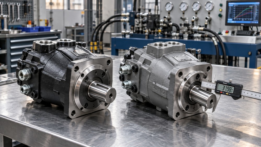
Compare pilot diameter, bolt-circle dimensions, hole size, flange thickness, and shaft projection from the mounting face. Confirm clearance for the housing, fittings, drain connection, and service access. A matching flange designation does not establish clearance for every housing option.
Shaft specifications require more than diameter. Check keyed or splined construction, spline standard and tooth count, key dimensions, taper, retaining method, and usable engagement length. A coupling that slides onto the shaft can still have inadequate engagement or bottom out before the mounting faces seat.
For a sprocket, pulley, or gear mounted directly on the motor, compare allowable radial load at the actual load position and operating speed. Also check axial load limits. Bearing capacity varies between motors with otherwise similar dimensions; moving a sprocket farther from the mounting face increases bending demand.
Ports, fittings, and rotation
Identify each connection by its thread and sealing system, not by visual similarity. Verify port size, pressure rating, orientation, and fitting clearance. Adapters may solve a connection mismatch, but they can introduce restrictions, interference, and additional leak points.
Confirm rotation using the manufacturer’s stated viewing direction, usually from the shaft end, and identify which pressurized port produces that rotation. Do not assume every motor is fully reversible or that swapping hoses preserves the function of an integrated brake, flushing valve, or anti-cavitation arrangement.
Use displacement, pressure drop, and efficiency together
Displacement connects flow to speed and pressure drop to torque. For preliminary comparisons, with displacement in cm³/rev, flow in L/min, and pressure drop in bar:
- Ideal speed: n = 1,000 × Q ÷ Vd
- Ideal torque: T = Δp × Vd ÷ (20π), in N·m
Actual motor speed depends on volumetric efficiency; actual output torque depends on mechanical efficiency. Use the candidate’s curves at the required operating point rather than applying an assumed efficiency to every condition. Starting torque and low-speed smoothness require separate attention, especially when the load must begin moving without a run-up.
As a calculation example, not a measured machine result, 40 L/min supplied to a 200 cm³/rev motor gives an ideal speed of 200 rpm. A 250 cm³/rev replacement at the same flow gives 160 rpm, while offering more theoretical torque at the same pressure drop. Equal mounting dimensions would not make those motors functionally interchangeable.
Use pressure differential across the motor, not inlet pressure alone. Return-line backpressure reduces the differential available for useful torque and may create separate housing or seal limitations. Compare continuous, intermittent, and peak ratings individually, including the manufacturer’s permitted durations and operating conditions. A peak rating does not authorize continuous operation.
Check the machine’s full operating envelope. A motor may meet maximum torque requirements but exceed its permitted speed during unloaded travel. Another may provide adequate running torque yet fail to start smoothly under load. Flow controls or relief adjustments should not be treated as automatic fixes: they can change heat generation, protection settings, and the behavior of other circuit functions.
Case drainage and load control can rule out an otherwise close match
Some motors drain internal leakage through a dedicated case connection; others use internal drainage arrangements within specified limits. These configurations are not automatically interchangeable. Check the permitted case pressure, shaft-seal pressure, required drain routing, and any mounting-position or case-filling instructions.
A replacement requiring an external drain needs a suitable low-pressure return path according to its installation instructions. Do not cap the drain or connect it to a convenient return line without assessing backpressure during cold starts, reversals, and simultaneous machine functions. A motor rated for high working pressure may tolerate only much lower pressure in its housing.
Keep the following limits distinct:
- Working-port pressure: allowable pressure at the hydraulic connections.
- Differential pressure: pressure difference used in torque calculations and performance limits.
- Case pressure: pressure acting within the housing and on relevant seals.
Winches, travel drives, and other overrunning applications need further circuit review. Verify compatibility with counterbalance valves, cross-port relief valves, replenishing checks, and brake-release circuits. Differences in leakage or displacement can affect load control. A motor with a holding brake also needs the correct brake torque, release pressure, and release sequence; matching the hydraulic motor’s torque alone is insufficient.
Closed-loop drives may additionally require compatible charge-pressure limits, flushing provisions, and control behavior. Replacing a variable-displacement motor requires confirmation of the displacement range, control signal, fail position, and feedback interfaces—not simply the maximum displacement.
Confirm fluid, seals, and thermal limits
Check the specified fluid type, viscosity range, operating temperature, and cleanliness requirement against the machine’s fluid and maintenance conditions. Compatibility with mineral hydraulic oil does not establish suitability for water-glycol, biodegradable, or fire-resistant fluids. Obtain confirmation for the actual fluid formulation and seal materials.
Cold-start viscosity and hot-running viscosity both matter. High viscosity can increase inlet and drain restrictions; low viscosity can increase internal leakage and reduce lubrication. Compare performance at realistic operating temperatures rather than relying only on catalog data taken under different test conditions.
A replacement with higher losses may also place additional demand on cooling capacity. Where a motor has failed, inspect for contamination, restricted return flow, misalignment, or overload before installing another unit. Otherwise, a compatible replacement may suffer the same damage.
Turn the comparison into an approval decision
Prepare a side-by-side record with the original specification, machine requirement, replacement specification, and supporting document for each critical item. Mark missing information as unresolved rather than assuming a match. Ask the supplier to identify deviations explicitly and confirm suitability for the stated duty, including external shaft loads and circuit conditions.
Classify the candidate as a direct replacement, an engineered substitution, or unsuitable. An adapter, new coupling, added drain line, or control adjustment makes the installation a substitution requiring documented review. Record those changes so future maintenance teams do not reorder against an incomplete description.
Validate the installation before returning it to service
Commissioning should follow the machine and motor manufacturers’ procedures. Isolate energy, release stored hydraulic pressure, and mechanically secure suspended or movable loads before installation. Pressure testing and work on load-holding circuits require qualified personnel and appropriately rated instrumentation.
- Inspect before startup. Confirm alignment, fastener torque, hose routing, coupling engagement, drain connection, fluid cleanliness, and any required case filling or air removal.
- Begin under controlled conditions. Where the equipment permits, verify rotation and low-load operation before increasing speed or load. Keep people clear of moving components and potential hose failures.
- Measure under representative duty. Record speed, pressure at both working ports, case pressure where applicable, temperature, and leakage behavior. Check starting, reversing, and braking functions relevant to the machine.
- Apply stop criteria. Stop for unexpected motion, abnormal noise, unstable speed, leakage, excessive temperature, or pressure outside the documented limits. Do not compensate by raising relief settings without engineering review.
Successful no-load rotation confirms only part of compatibility. Release the equipment only after required loaded operation and safety functions have been verified against documented acceptance limits. Retain the approved motor code, drawings, settings, and test readings with the maintenance record so the next replacement starts from a verified specification.
Want to dive deeper into these market dynamics, or need data-driven support for your next business move? Drop a line below and let the analysts at PCTS provide customized insights.
We respect your privacy. Your information is strictly confidential.
Related News
- 00
0000-00
How to assess a chain and belt drive manufacturer's quality control - 00
0000-00
How intelligent condition monitoring detects conveyor bearing faults - 00
0000-00
How misalignment affects belt drive components - 00
0000-00
Trelleborg Sealing Solutions Uses AI to Optimize Rotary Shaft Seal Design - 00
0000-00
How turbine operating speed affects precision bearing selection
Weekly Insights
Stay ahead with our curated technology reports delivered every Monday.