





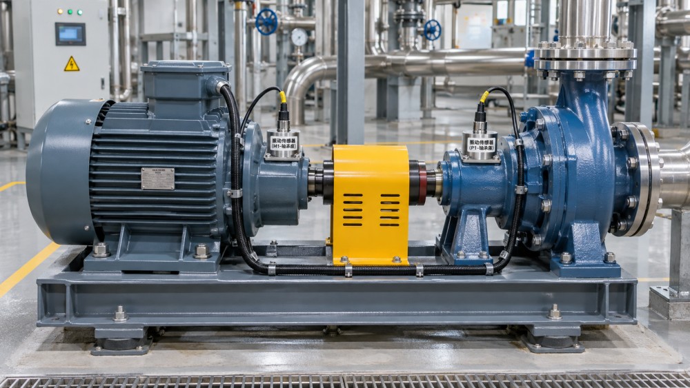
Install vibration sensors on the bearing housings or bearing supports of rotating machinery, as close as practical to the bearings carrying the shaft. On a typical motor-driven pump, that means considering both the motor and pump bearings, with measurement directions chosen to capture radial and axial movement. Start with the bearings most exposed to failure or most consequential to operation, then add points where the machine layout leaves a meaningful gap in coverage.
A convenient flat surface is not automatically a useful measurement point. The sensor needs a solid vibration path from the component being monitored, enough access for secure mounting, and a location that can be measured consistently. The best arrangement also depends on whether the team is collecting periodic readings, installing permanent sensors, or investigating a specific fault.
Start at the bearings and follow the load path
Bearings transmit shaft vibration into the surrounding structure. A sensor on a rigid bearing housing can therefore capture useful information about bearing condition as well as movement associated with imbalance, misalignment, looseness, and other faults. The signal generally becomes harder to interpret when it has to travel through joints, thin covers, or large sections of the machine before reaching the sensor.
For a motor, identify the drive-end bearing nearest the coupling or pulley and the non-drive-end bearing at the opposite end. For a pump, fan, gearbox, or other driven machine, identify its bearing locations separately. A coupling connects the machines, but a sensor on the motor does not provide the same view as one mounted near the driven machine’s bearing.
Place each sensor on a rigid part of the housing, as close to the bearing load zone as the design and access allow. The mounting surface should be part of the bearing support, not a removable guard, sheet-metal cover, or conduit box. Avoid assuming that the nearest visible surface is attached directly to the bearing housing: on some machines, a cover can sit close to a bearing while offering a poor vibration path.
When access is limited, trace the mechanical path from the bearing to the proposed mounting point. A thick, continuous housing is generally preferable to a location across a split joint or attached bracket. If the best point is inaccessible, document the compromise and use the same point for future measurements so changes can still be evaluated in context.
Choose directions that show how the machine moves
Location and measurement direction work together. A sensor on the correct bearing housing can miss useful information if it measures only a direction in which the fault produces little response. For a horizontal shaft, maintenance teams commonly describe readings as horizontal radial, vertical radial, and axial.
- Horizontal radial: Measures movement perpendicular to the shaft and parallel to the floor. It can be useful for observing lateral movement of a machine on its supports.
- Vertical radial: Measures movement perpendicular to the shaft and toward or away from the floor. It helps show how the bearing and supporting structure respond vertically.
- Axial: Measures movement parallel to the shaft. It can be useful when investigating alignment, thrust-related behavior, or other sources of end-to-end movement.
These directions are starting points, not fault labels. High axial vibration alone does not prove misalignment, and a strong radial reading does not by itself prove imbalance. Compare directions, operating conditions, frequency information, and other inspection findings before deciding on corrective work.
For periodic route measurements, collecting readings in more than one direction at accessible bearings provides a fuller picture. A single-axis permanently mounted sensor measures along its sensitive axis, so its orientation must be deliberate. If only one sensor can be installed at a bearing, choose the direction based on the expected failure modes, machine stiffness, previous measurement history, and access. A triaxial sensor can collect three directions at one point, provided its mounting and frequency performance are appropriate for the monitoring task.
On vertical machines, define directions relative to the shaft and a fixed plant reference rather than relying on “horizontal” and “vertical” labels alone. Mark the directions on the route sheet or monitoring system so another technician can repeat the measurement correctly.
Practical locations on common machine arrangements
Motor-driven pumps
For a coupled motor and pump, map the motor drive-end and non-drive-end bearings, then locate the pump bearings. Measure on each bearing housing where access permits. The pump drive-end bearing near the coupling is often a useful point, but it should not be treated as a substitute for the motor drive-end bearing on the other side of the coupling.
On an overhung pump, pay particular attention to the pump bearing arrangement and the support nearest the impeller. Hydraulic conditions can influence vibration, so record flow, valve position, and other relevant operating conditions when comparing readings. A change in vibration after a process adjustment does not necessarily indicate a change in bearing condition.
Fans and belt-driven equipment
For a belt-driven fan, measure at the motor bearings and the fan shaft bearings. The bearings supporting the fan shaft are especially relevant to the fan assembly; a motor-mounted sensor may not capture their behavior clearly through the belt drive.
Record sensor directions relative to the shaft and note the belt pull direction. Belt tension, pulley condition, structural looseness, and fan deposits can all affect the observed response. Avoid mounting on the fan casing merely because it is easy to reach; use the bearing housing or a rigid bearing support whenever possible.
Gearboxes
Locate sensors near the gearbox input and output shaft bearings, using solid housing surfaces with a short path to the bearing or gear stage of interest. A larger gearbox with several shafts may need additional points to distinguish which stage is changing. A single reading on the outside of the casing can be useful for trending, but it may not provide enough information to identify the source of a problem inside.
Gear-related signals can contain higher-frequency content than overall machine vibration. Select a sensor, mounting method, and measurement settings suited to the frequencies being investigated. A point that works for a general vibration trend may be less effective for detailed bearing or gear analysis if the mounting surface or attachment filters the signal.
Make the mounting point part of the measurement
The way a sensor is attached can change the reading as much as a small change in location. A stable, rigid connection helps preserve the vibration signal, particularly at higher frequencies. Follow the sensor manufacturer’s mounting requirements and the machine manufacturer’s restrictions before modifying a housing.
For permanent monitoring, a properly prepared, flat mounting surface and a stud attachment are often suitable where drilling and tapping are permitted. Use the specified mounting hardware and tightening method. Do not drill into a bearing housing without checking what lies behind the surface, including oil passages, cavities, seals, and bearing clearances.
Adhesive mounting pads can provide an alternative where a stud cannot be used, provided the adhesive, surface preparation, temperature range, and sensor system are compatible. A magnetic mount can be practical for route-based measurements on a clean, flat ferromagnetic surface, but its frequency response depends on the magnet, contact surface, and sensor assembly. A handheld probe is convenient for a quick check but is less repeatable because contact pressure and angle can vary.
Remove loose paint, corrosion, and contamination as required by the mounting method. Ensure the sensor sits firmly against the prepared surface. Route cables away from moving parts, hot surfaces, sharp edges, and electrical interference sources, and provide strain relief so cable movement does not disturb the sensor. Wireless devices also need a secure mount and a position that supports dependable communication without compromising the measurement point.
For hazardous areas, high temperatures, washdown exposure, or other demanding conditions, use equipment and installation methods suitable for the location. Isolate and secure machinery before accessing mounting points, following the site’s procedures.
When coverage is limited, prioritize deliberately
Permanent sensors are not always practical at every bearing. Begin with machines whose failure would have the greatest operational or safety consequence, then consider the bearings most difficult to inspect or most relevant to the expected fault. A critical pump bearing with poor routine access may deserve continuous coverage before an easily reached motor bearing on a noncritical standby machine.
Within a machine, use existing fault history and the mechanical layout to select points. If the main concern is a driven-machine bearing, place the sensor on that bearing’s support rather than relying solely on a convenient motor location. If the concern spans several components, a single sensor may support an overall trend while leaving the team dependent on follow-up measurements to locate the source.
Keep enough route-based measurements to check locations and directions that permanent sensors do not cover. This is particularly useful after a sensor reports a change: comparing adjacent bearings and directions can help determine whether the response is local or being transmitted through the assembly.
Establish a repeatable baseline
Once the sensors are installed, record each measurement point by machine, bearing, location, and direction. Include a photograph or sketch in the maintenance record, along with the sensor type, mounting method, measurement settings, and any known access limitations. Labels such as “motor vibration” are too broad when a later technician needs to distinguish drive end from non-drive end.
Collect baseline data under representative operating conditions and record speed, load, and relevant process conditions. Variable-speed equipment may need readings associated with different operating points; comparing a low-load reading with a full-load reading can make an ordinary operating change look like a developing fault.
After maintenance, check that sensors and cables have been reinstalled securely and that the same measurement settings are in use. If a sensor is moved or its mounting method changes, note that in the trend history. A reliable comparison depends on knowing that the measurement still represents the same bearing, direction, and operating condition.
Want to dive deeper into these market dynamics, or need data-driven support for your next business move? Drop a line below and let the analysts at PCTS provide customized insights.
We respect your privacy. Your information is strictly confidential.
Related News
- 00
0000-00
How to assess a chain and belt drive manufacturer's quality control - 00
0000-00
How intelligent condition monitoring detects conveyor bearing faults - 00
0000-00
How misalignment affects belt drive components - 00
0000-00
Trelleborg Sealing Solutions Uses AI to Optimize Rotary Shaft Seal Design - 00
0000-00
How turbine operating speed affects precision bearing selection
Weekly Insights
Stay ahead with our curated technology reports delivered every Monday.