





How Cleanroom Pneumatic Design Prevents Particle Contamination
Pneumatic automation is valued for fast cycling, compact installation, simple force control, and safe operation in many industrial environments. Inside a cleanroom, however, those same systems require much closer scrutiny. A cylinder that performs reliably on a conventional assembly line may release particles, aerosols, lubricant residues, or wear debris at levels that are unacceptable near wafers, optical assemblies, medical devices, batteries, or sterile packaging operations.
Cleanroom pneumatic design is therefore not just a matter of selecting a “clean” actuator. It is a system discipline covering compressed-air quality, material compatibility, seal behavior, exhaust management, motion profile, installation details, and maintenance practices. The engineering question is not whether a pneumatic component can move a load. It is whether it can do so repeatedly without becoming a source, pathway, or amplifier of contamination.
For manufacturers evaluating pneumatic equipment, the most useful starting point is to separate contamination generated inside the device from contamination carried through the device. Internal generation commonly comes from seal wear, guide wear, abrasion between moving surfaces, residual lubricant, and particle release during end-of-stroke impact. Transported contamination may originate upstream in the compressed-air network: corrosion products, oil aerosols, condensate, pipe-scale particles, or filter breakthrough can all reach the point of use. Both mechanisms must be controlled together.
The pneumatic system is part of the contamination control strategy
Cleanroom classification is generally considered at room level, while pneumatic devices are assessed as contributors within a particular process zone. ISO 14644 is widely used as a framework for airborne particle cleanliness in cleanrooms and controlled environments. It does not eliminate the need to examine the specific machine arrangement, process sensitivity, airflow direction, and operating duty cycle. A component acceptable in an outer equipment enclosure may not be acceptable above an open process, close to a substrate, or within a mini-environment with tightly controlled airflow.
This distinction matters because particle behavior is local. A rodless cylinder mounted away from a critical surface, with exhaust ducted outside the controlled zone, presents a different risk from a vertically mounted actuator operating directly over exposed product. Supply-air cleanliness alone cannot compensate for mechanically generated debris at the point of motion. Conversely, a carefully designed low-shedding cylinder can still contaminate its surroundings if the air distribution system delivers oil or moisture to it.
Airflow also changes the practical result. Uncontrolled exhaust can disturb laminar flow, entrain settled particles, or carry microscopic debris into a sensitive process area. Cleanroom layouts should consider where air is exhausted, not merely where an actuator is installed. In many designs, an external exhaust connection, a controlled collection path, or positioning the valve island outside the highest-cleanliness zone is more valuable than a minor improvement in nominal actuator specifications.
Start with air quality, then protect it to the point of use
Compressed air is often described as the utility behind pneumatic motion, but in a clean process it is also a potential contamination stream. The relevant air-quality target should be defined for the application rather than assumed from the presence of a central compressor room. ISO 8573-1 provides a commonly referenced classification system for compressed-air contaminants, including particles, water, and oil. The appropriate class depends on the process, the equipment supplier’s requirements, and whether the air can contact product or enter a critical enclosure.
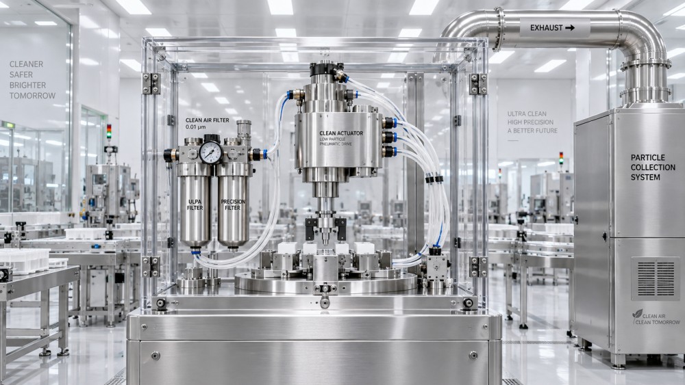
A robust arrangement often includes staged treatment: removal of bulk water and particulates upstream, coalescing filtration where oil aerosol control is required, and final point-of-use filtration near sensitive equipment. Yet filters are not permanent guarantees. Pressure differential, replacement interval, housing integrity, seal condition, bypass risk, and installation orientation all affect actual performance. A filter placed far from the machine can be followed by contaminated piping, poorly cleaned fittings, or maintenance work that reintroduces debris.
Materials used in downstream piping deserve similar attention. Old metallic distribution lines can generate corrosion particles, while inappropriate flexible tubing can shed, outgas, kink, or retain contaminants. Tubing, fittings, regulators, gauges, and quick-connects should be reviewed as a connected flow path. A technically sound cleanroom pneumatic design specifies what happens after treatment, including how the line is cleaned, capped during installation, and protected when equipment is modified.
Oil-free compression does not automatically mean oil-free air at the point of use. Ambient hydrocarbons, compressor-room conditions, downstream lubricators, and maintenance practices can still affect air quality. The objective is not a label; it is documented control of the actual air stream reaching the pneumatic circuit.
Where particles are generated inside actuators
Every sliding pneumatic mechanism has friction interfaces. Piston seals contact cylinder bores; rod seals contact moving rods; guides manage side loads; cushions decelerate moving masses; grippers may include jaws, bearings, and return springs. Particle control begins by reducing unnecessary friction and preventing operating conditions that accelerate wear.
Seal selection is central. Elastomer and polymer formulations differ in abrasion resistance, chemical compatibility, temperature capability, friction characteristics, and behavior with particular lubricants. There is no universally correct seal material. A low-friction seal may be appropriate for rapid, lightly loaded cycles but unsuitable for cleaning chemicals, elevated temperature, or extended dwell periods. For applications exposed to aggressive media or demanding thermal conditions, the seal choice should be evaluated alongside its wear mechanism rather than treated as a simple material upgrade.
Lubrication requires equally careful judgment. Conventional pneumatic components may rely on factory-applied grease to reduce friction and extend service life. In clean environments, excessive lubricant can migrate, attract particles, or create an unacceptable molecular contamination concern. Cleanroom-oriented actuators may use controlled amounts of compatible lubricant, specialized sealing arrangements, or construction intended for operation without supplemental lubricated air. Removing lubrication indiscriminately is not a solution: it can increase seal wear and shorten component life. The operating instructions for the selected component and the process contamination limits must be reconciled before commissioning.
Side loading is a frequent, preventable cause of wear. A cylinder used as both actuator and structural guide can experience uneven seal contact, rod scoring, and guide deterioration. External linear guides, correct load alignment, and properly designed mounting interfaces reduce this risk. The same principle applies to grippers: jaw forces, payload center of gravity, and external moments should be checked instead of relying only on the nominal gripping force.
End-of-stroke impact is another overlooked source of debris. High-speed travel followed by abrupt mechanical contact can produce wear at cushions, bumpers, stops, and fixtures. Proper pneumatic cushioning, flow control, and motion profiling reduce the severity of the event. A short cycle time is not necessarily a clean cycle time. The best operating profile is often the fastest stable motion that avoids violent deceleration, uncontrolled vibration, or repeated hard stops.
Architecture choices shape the exposure risk
The physical architecture of the automation cell determines whether generated particles can reach a critical area. Engineers commonly use separation as a primary control method: place valves, regulators, manifolds, and higher-wear elements outside the cleanest zone where practical; transmit motion through a suitable boundary; and keep the most sensitive process area free of nonessential moving parts.
When an actuator must be located inside the enclosure, details become consequential. A covered or enclosed profile can limit direct particle release, but covers must themselves be compatible with airflow, cleaning access, and maintenance. Rod orientation, mounting direction, and gravity can influence where residues settle. For vertical axes over product, designers should be particularly cautious about any component that can release particles downward. A well-designed local airflow pattern may help carry emissions away, but it should be demonstrated in the actual machine configuration rather than assumed from a general layout drawing.
Vacuum generation is often linked to pneumatic handling and deserves separate review. Venturi vacuum generators consume compressed air and exhaust it, sometimes near the handled object. Depending on the application, a remotely mounted generator, electrically driven vacuum source, or routed exhaust may offer better contamination control. The right decision depends on cycle rate, vacuum demand, heat load, available utilities, acoustic limits, and the sensitivity of the handled material.
Specify evidence, not vague claims
Terms such as “cleanroom compatible” can be useful, but they are not a complete engineering specification. Technical evaluation should ask what was tested, how it was tested, and under what operating conditions. A supplier statement may apply only to a particular product series, mounting orientation, lubricant option, pressure range, or test cycle. It may not represent the final assembly with fittings, sensors, cable carriers, tooling, and exhaust hardware installed.
Useful documentation can include particle-emission test information, recommended operating conditions, material declarations, lubricant details where available, cleaning guidance, dimensional data for exhaust connections, and stated maintenance limits. The test method itself matters: particle size range, background cleanliness, sampling position, actuator load, velocity, cycle count, and enclosure configuration can materially change results. Comparisons are meaningful only when these conditions are sufficiently similar.
Maintenance can preserve or defeat the original design
A pneumatic system may enter service in a clean condition and gradually become a contamination source through routine intervention. Opening fittings without clean handling, replacing an approved tube with a visually similar alternative, using an unsuitable thread compound, or adding an unapproved lubricator can undo the original contamination-control approach. Maintenance documentation should identify approved replacement parts and clearly distinguish components that may be serviced in place from those that require controlled removal.
Condition monitoring is useful when applied to relevant failure modes. Rising breakaway pressure, increased cycle time, unstable positioning, abnormal exhaust behavior, and higher pressure drop across filters may signal degradation before a mechanism visibly fails. These indicators do not replace particle monitoring where process requirements demand it, but they help maintenance teams investigate abnormal wear early. In high-value production environments, planned replacement based on documented duty and observed condition is often preferable to waiting for a pneumatic device to seize, leak, or shed debris near product.
This is one reason component selection cannot be isolated from MRO planning. Seal availability, filter change procedures, spare actuator configuration, supplier documentation, and the ability to maintain configuration control all affect long-term cleanliness. A low initial component cost can become less attractive if the replacement process is difficult to validate or introduces uncertainty into a controlled process.
A practical review before release
Before approving a cleanroom pneumatic design, it is worth reviewing the complete chain: compressor and treatment equipment, downstream distribution, point-of-use filtration, valve location, actuator construction, exhaust routing, mechanical loading, local airflow, and maintenance access. The critical question is always application-specific: if a component wears or releases air at this exact location, where will the resulting material travel?
PCTS approaches these questions through the connected disciplines of pneumatic components, sealing technology, mechanical motion, reliability, and industrial MRO. That wider view is useful because contamination risk rarely belongs to one catalogue item. It usually emerges at the interfaces between air quality, seals, moving hardware, assembly practice, and replacement decisions. For sensitive equipment, the next step should be to compare supplier documentation against the actual duty cycle and cleanliness requirements, then validate the completed machine configuration rather than relying on a component description alone.
Related News
- 00
0000-00
How cleanroom pneumatic design prevents particle contamination - 00
0000-00
How to select seals for abrasive mining equipment components - 00
0000-00
What a sealing failure analysis report should reveal about root cause - 00
0000-00
How fluid power component design affects energy efficiency in machines - 00
0000-00
How hydraulic contamination shortens the life of mining equipment parts
Weekly Insights
Stay ahead with our curated technology reports delivered every Monday.