





Fluid power systems are often assessed by their force, speed, controllability, and robustness. Energy efficiency is sometimes treated as a secondary outcome. In practice, it is designed into the machine long before commissioning. A hydraulic pump that is oversized for the duty cycle, a valve with an unnecessarily restrictive flow path, or a pneumatic circuit that vents compressed air on every cycle can create losses that controls software cannot fully recover.
Fluid Power Component Design determines how effectively input energy becomes useful linear motion, rotary torque, or controlled holding force. The relevant losses are not limited to one part. They occur through leakage, pressure drop, mechanical friction, fluid agitation, throttling, heat generation, compressed-air waste, and poor matching between component capability and the real load profile. For machinery teams comparing alternatives, the useful question is not simply “which component has the highest catalogue efficiency?” It is “which design maintains acceptable efficiency across the machine’s actual operating points, environmental conditions, and service life?”
Efficiency begins with the energy path, not the individual component
A fluid power circuit converts prime-mover energy into fluid energy, directs that energy through conductors and control elements, and finally turns it into useful actuator work. Every transition has a loss mechanism. In hydraulics, pump volumetric losses, internal leakage, bearing and slipper friction, valve throttling, hose friction, and cylinder seal drag all contribute. In pneumatics, the energy cost begins even earlier at air compression, treatment, storage, distribution, and leakage before air reaches a valve island or actuator.
This is why a component should not be evaluated in isolation. A low-pressure-drop valve can be counterproductive if its large flow capacity makes stable low-flow control difficult. A cylinder with low seal friction may be unsuitable if its sealing configuration cannot tolerate the fluid, side load, temperature, or contamination level. Conversely, a component with a modestly higher initial cost can reduce operating losses and unplanned maintenance if it better matches the duty cycle.
For hydraulic equipment, overall efficiency is generally considered as a combination of volumetric and mechanical or hydromechanical efficiency. Volumetric efficiency reflects how much theoretical displacement becomes delivered flow or actuator motion; mechanical efficiency reflects the torque or force lost to friction and internal drag. A system may perform well when cold and lightly loaded, then lose efficiency as viscosity falls, clearances wear, or internal leakage increases. The point is not to seek a single perfect figure, but to request efficiency curves at relevant pressure, speed, temperature, and viscosity conditions.
Pump and motor geometry set the baseline in hydraulic machines
Hydraulic pump selection has a disproportionate effect on machine energy use because it establishes the available flow and pressure. Fixed-displacement pumps can be appropriate where demand is steady and predictable. However, if a fixed pump continuously produces flow that is later throttled across a valve or relieved back to tank, the machine converts useful electrical or engine power into heat. This arrangement may be simple and dependable, but it should be justified by the duty cycle rather than inherited from an older design.
Variable-displacement piston pumps can reduce unloaded or part-load losses by matching output to demand, particularly in systems with long dwell periods or widely varying flow requirements. Their efficiency still depends on compensator settings, swash-plate control behavior, fluid cleanliness, case-drain management, and the pressure stability required by the process. A pressure-compensated pump set to maintain a high standby pressure may reduce flow loss while retaining considerable standby energy consumption. Load-sensing architectures can improve this condition, but only when sensing lines, valve margins, pump control response, and actuator priorities are engineered as a system.
Hydraulic motors deserve the same scrutiny. Shaft speed, starting torque, case pressure limits, bearing loads, and expected reversals influence the useful operating envelope. Running a motor far below or above its efficient speed range can increase leakage or frictional losses. Where a motor drives a gearbox, belt, chain, or coupling, those downstream transmission losses must also be included. A highly efficient motor cannot compensate for misaligned couplings, excessive belt tension, or bearings operating with poor lubrication.
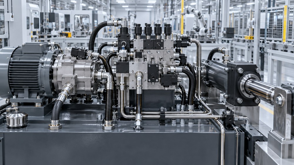
Valves and flow paths: where controllability often becomes heat
Pressure drop is a normal consequence of moving fluid through ports, passages, hoses, fittings, filters, and valves. It becomes an energy problem when it is needlessly high or when designers rely on throttling as the primary method of speed control. The lost power appears mainly as heat, which then raises the burden on the reservoir, cooler, seals, lubricant properties, and maintenance schedule.
Valve design choices matter at a detailed level: spool land geometry, metering-notch profile, nominal flow rating, port size, pilot arrangement, response time, and leakage characteristics all affect the balance between precision and loss. A proportional valve may support smoother control and reduce overshoot in a variable process, but its benefit depends on control tuning and a stable hydraulic supply. An on/off valve may be more efficient in a discrete operation if it avoids continuous throttling. There is no universal winner; the load profile decides.
Flow-path design should also look beyond the manifold block. Long runs, sharp bends, undersized quick couplings, restrictive return lines, and poorly sized filters can create persistent pressure losses. Return-line backpressure is particularly easy to overlook because the actuator still appears to move. Yet elevated return pressure can increase seal stress, raise case pressure, and reduce the available pressure differential across the useful load.
A practical review traces pressure from pump outlet to actuator and back to tank at each key operating state: acceleration, steady motion, peak load, regeneration, deceleration, and idle. This often reveals that the nominal circuit diagram hides the most expensive restriction.
Cylinder, actuator, and seal design affect both leakage and usable force
Cylinder efficiency is not just a bore-and-stroke calculation. Piston seal friction, rod seal lip geometry, guide-ring material, surface finish, rod coating, alignment, and side loading determine how much pressure is needed to initiate and sustain motion. Breakaway friction can be especially important in low-speed positioning applications. If it is high or inconsistent, the control system may repeatedly overshoot and correct, wasting energy while reducing motion quality.
Internal leakage reduces holding performance and forces the pump to make up flow. External leakage is more visible, but it is not the only concern. A seal package designed solely for low friction may have limited durability in abrasive, high-temperature, chemically aggressive, or poorly lubricated environments. The better design target is stable friction and controlled leakage over the anticipated service interval.
Material compatibility should be checked against the actual hydraulic fluid, additives, temperature range, pressure cycling, and contamination exposure. Nitrile, fluorocarbon, polyurethane, PTFE-based materials, and engineered elastomers each have different strengths and limitations. A material choice cannot be validated by a generic statement such as “oil resistant.” Compatibility data from the seal supplier and the fluid supplier should be reviewed together, especially where biodegradable fluids, fire-resistant fluids, solvents, or high-temperature conditions are involved.
For pneumatic cylinders, cushioning design and end-of-stroke behavior matter. Excessive impact wastes energy through vibration and can damage mounts; overly restrictive cushioning may slow the cycle or demand higher supply pressure. Adjustable cushioning, external shock absorbers, and controlled deceleration should be assessed against cycle rate and load inertia rather than selected as routine options.
Pneumatic efficiency requires a different mindset
Pneumatics is often chosen for cleanliness, simplicity, fast action, and safe operation in certain environments, not because compressed air is inherently the lowest-energy utility. Its efficiency depends heavily on avoiding unnecessary air generation and pressure. Raising plant pressure to solve one poorly performing actuator can increase demand across a wider network. It is usually better to investigate local restrictions, cylinder sizing, friction, valve flow capacity, regulator setting, and leakage first.
Component design can reduce consumption through shorter dead volumes, appropriate valve placement, well-sized tubing, low-leakage fittings, and actuator sizing that avoids excessive bore area. Vacuum generation deserves special attention. Venturi devices can be compact and convenient, but continuous vacuum generation or uncontrolled blow-off can consume substantial compressed air. Vacuum switches, shut-off strategies, accumulator arrangements, and alternative vacuum technologies may be worth evaluating where the duty cycle is long.
Air preparation is another trade-off. Filters, regulators, lubricators where applicable, dryers, and condensate management protect components but add pressure loss. The objective is not to remove every restriction; it is to provide the required air quality with the lowest stable pressure drop. A clogged filter indicator should be treated as an efficiency signal as well as a maintenance signal.
Design for the duty cycle, then verify against standards and service conditions
A component comparison should begin with a realistic duty profile rather than maximum nameplate conditions alone. Record force or torque demand, speed, motion frequency, dwell periods, pressure peaks, ambient temperature, fluid or air quality, load direction, and expected life. Include abnormal but credible conditions such as cold starts, high backpressure, emergency stops, contamination events, and frequent low-load cycling. These are often where apparently efficient designs become unstable or maintenance-intensive.
Safety and documentation should remain part of the evaluation. ISO 4413 provides general rules and safety requirements for hydraulic fluid power systems, while ISO 4414 addresses pneumatic systems and their components. These standards do not select a component for a particular machine, but they help frame considerations such as pressure containment, isolation, unexpected movement, stored energy, and documentation. Requirements should be checked against the applicable edition, machinery risk assessment, customer specifications, and local regulations.
Fluid cleanliness is also linked to energy performance. Wear particles can increase leakage, damage metering edges, and alter pump or valve behavior long before a complete failure occurs. Where hydraulic cleanliness is specified, ISO 4406 coding is commonly used to communicate particulate contamination levels. The appropriate target depends on component sensitivity and system design; copying a cleanliness class from an unrelated machine is not a reliable engineering method.
Condition monitoring protects the original efficiency assumption
Even a well-designed circuit drifts over time. Rising pump case drain, increased cylinder bypass, changing pressure differential across filters, compressor loading patterns, temperature trends, and longer cycle times can all indicate that energy losses are growing. Monitoring need not mean instrumenting every connection. It means selecting measurements that reveal whether the original design envelope is being maintained.
A pressure sensor before and after a filter, combined with temperature and flow data where justified, can distinguish a restriction problem from a load change. In pneumatic systems, pressure measurement near the point of use can reveal distribution losses that a compressor-room gauge cannot show. Leakage surveys are valuable, but their findings should lead to structured repair and verification; otherwise the same losses return as fittings age or machine modifications accumulate.
This systems perspective is central to the work covered by Global Precision Components & Transmission Systems (PCTS). Fluid power performance intersects with bearings, seals, couplings, mechanical transmission, tribology, sensing, and MRO planning. Looking across these interfaces helps teams avoid the common mistake of treating heat, leakage, vibration, and lost productivity as separate problems when they share a mechanical or fluid-power cause.
The most useful selection question
The best Fluid Power Component Design is rarely the design with the lowest individual pressure drop, the tightest clearance, or the most advanced control feature. It is the design that delivers required motion and safety with manageable losses across normal operation, transient events, and the expected maintenance interval.
Before approving a component, compare supplier data at realistic operating points, review seal and fluid compatibility, map the full flow path, and ask what happens when the machine is cold, dirty, lightly loaded, or held at standby. Those checks turn energy efficiency from a catalogue claim into an engineering decision that can be maintained in the field.
Want to dive deeper into these market dynamics, or need data-driven support for your next business move? Drop a line below and let the analysts at PCTS provide customized insights.
We respect your privacy. Your information is strictly confidential.
Related News
- 00
0000-00
How to check vibration analysis software for sensor compatibility - 00
0000-00
IndexBox Forecasts 3.8% Annual Growth for Global Radial Seals Market Through 2035 - 00
0000-00
How to assess the chemical compatibility of FFKM sealing sheets - 00
0000-00
IndexBox Forecasts 3.6% Annual Growth for Construction Bearings Market - 00
0000-00
When do hydraulic components require an export license?
Weekly Insights
Stay ahead with our curated technology reports delivered every Monday.