





Why does wind turbine bearings fatigue often appear before anyone sees visible damage?
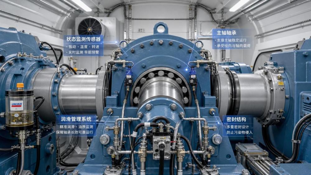
Wind turbine bearings fatigue rarely starts with dramatic cracking. In many cases, the first changes happen at the surface and below it.
That is why early diagnosis matters. By the time flaking is obvious, the bearing has usually been operating under harmful conditions for months.
In practical terms, wind turbine bearings fatigue is a progressive damage process caused by repeated stress cycles, unstable lubrication, contamination, and load distortion.
Main shaft, pitch, yaw, and gearbox bearings all face different duty patterns. Yet the fatigue logic is similar: local stress rises, film protection weakens, and surface damage accelerates.
A useful way to read the problem is through system behavior, not only bearing failure images. Tribology, sealing condition, alignment, and load control all influence fatigue life.
This broader view is increasingly reflected across industrial intelligence platforms such as PCTS, where bearing performance is evaluated together with lubrication, sealing, transmission, and MRO economics.
So when people search for wind turbine bearings fatigue, they are usually asking a deeper question: what starts the damage early, and what evidence appears soon enough to act?
What are the earliest warning signs worth taking seriously?
The earliest signs are usually indirect. Operators often expect visible spalls, but fatigue begins with small changes in friction, vibration, and surface condition.
Micropitting is one of the most common early indicators. It appears as fine surface distress caused by repeated asperity contact and inadequate lubricant film separation.
Another clue is rising vibration at frequencies linked to rolling contact defects. The increase may be small, but trend growth matters more than one isolated reading.
Grease discoloration, metal particles in oil, and water content shifts also deserve attention. These signs suggest the contact environment is becoming hostile.
Temperature can help, but it is less specific. A warm bearing does not always indicate fatigue, while a damaged bearing may still run within expected temperature limits.
A more reliable approach combines several signals. The table below helps separate early fatigue clues from later-stage symptoms.
In short, the best early warning system is not one sensor. It is a pattern of small deviations that point to deteriorating rolling contact conditions.
Where do the root causes usually begin: design, lubrication, loading, or contamination?
The honest answer is often all four. Wind turbine bearings fatigue is usually multi-causal, and the visible failure mode may hide the original trigger.
Lubrication breakdown is one of the most common starting points. If viscosity is wrong, grease aging is advanced, or relubrication intervals drift, surface separation becomes unstable.
Contamination is equally damaging. Water, dust, wear debris, and process particles can indent raceways, disturb film formation, and create local stress risers.
Load distribution problems come next. Wind turbines operate under variable axial and radial loads, transient shocks, misalignment, and low-speed oscillation.
That makes false brinelling, edge loading, and sliding more likely. Once the contact patch is distorted, fatigue develops faster than nominal life calculations suggest.
Design and specification errors also matter. A bearing can be high quality and still be wrong for the duty cycle if internal clearance, preload strategy, coating, or sealing concept is poorly matched.
In actual field reviews, the most useful question is not which cause sounds most familiar. It is which cause best explains the damage pattern, operating history, and lubricant evidence together.
Common root-cause combinations seen in wind applications
- Micropitting plus darkened lubricant often points to film collapse and surface sliding.
- Edge damage with asymmetrical wear usually suggests misalignment or housing distortion.
- Corrosion marks with fatigue spalls often indicate water ingress through inadequate sealing.
- Early white etching features may involve transient loads, metallurgy sensitivity, and electrical effects.
Are all turbine bearings exposed to the same fatigue risk?
Not at all. Wind turbine bearings fatigue appears differently depending on the bearing position and motion profile.
Main shaft bearings usually face high loads, variable direction, and difficult lubrication conditions. Damage often grows from uneven load zones and lubricant starvation.
Pitch bearings work under oscillating motion rather than continuous rotation. That increases the risk of false brinelling, fretting, and localized fatigue in limited contact regions.
Yaw bearings can suffer from contamination, uneven bolt tension, and shock loading during directional adjustment. Surface distress may develop long before clear structural symptoms appear.
Gearbox bearings add another layer. Their risk is closely tied to lubrication cleanliness, transient torque, surface finish, and roller skidding behavior.
This is why comparison across bearing locations matters. An inspection plan that works for pitch bearings may miss the early mechanisms affecting the main shaft or gearbox.
PCTS-style cross-component analysis is useful here because bearing fatigue rarely exists in isolation. Seals, sensors, couplings, and lubrication practices all shape the actual risk profile.
How can wind turbine bearings fatigue be confirmed before failure becomes expensive?
Confirmation usually comes from layered evidence, not one dramatic test result. The goal is to build confidence early enough to plan action rather than react to a breakdown.
A sensible workflow starts with trend monitoring. Compare vibration, temperature, lubricant condition, and operating hours against each bearing position’s known baseline.
Next, review lubricant samples carefully. Viscosity shift, oxidation, water presence, and ferrous debris often reveal whether fatigue is being accelerated by contamination or film loss.
Inspection data should then be matched with mechanical context. Mounting condition, shaft deflection, preload condition, housing geometry, and sealing integrity all affect interpretation.
Where uncertainty remains, surface imaging and teardown evidence help distinguish true rolling fatigue from smearing, corrosion, indentation, or electrical erosion.
A practical diagnostic sequence often looks like this:
- Check trend deviations rather than one-time alarm values.
- Link condition data to the exact bearing position and duty cycle.
- Verify lubricant and seal condition before blaming bearing material.
- Review load path and alignment evidence for stress concentration.
- Use failure morphology only after operating history is understood.
This method reduces false conclusions. It also supports better replacement timing, spare planning, and vendor comparison.
What decisions actually reduce fatigue risk over the bearing lifecycle?
The strongest results usually come from disciplined specification and maintenance choices, not from one corrective action after a failure report.
Start with application fit. Internal geometry, clearance, coating options, cage design, and seal compatibility should reflect real load reversals and low-speed operating behavior.
Then look at lubrication as a controlled process. Grease type, oil cleanliness, replenishment interval, and temperature stability should be documented, reviewed, and adjusted by evidence.
Sealing strategy deserves equal attention. A strong bearing specification can still underperform if moisture and particles enter the contact zone repeatedly.
Condition monitoring should also be practical. The best program is one that connects sensor data with actionable thresholds and maintenance decisions.
To make those choices easier, this quick reference can be used during evaluation.
The key point is simple. Wind turbine bearings fatigue should be managed as a system risk, not treated as an isolated part defect.
So what is the most useful next step when fatigue risk is suspected?
Begin with evidence ranking. Separate what is known, what is suspected, and what still needs confirmation from inspection or lubricant analysis.
Then build a short decision file for the affected bearing position. Include operating history, load events, lubricant records, seal condition, and monitoring trends.
That makes comparison easier when reviewing alternative bearings, revised lubrication intervals, or upgraded sealing approaches.
For teams using broader industrial reference sources such as PCTS, the value lies in connecting bearing fatigue evidence with related knowledge on tribology, sealing, transmission reliability, and MRO planning.
Wind turbine bearings fatigue is rarely caused by one dramatic mistake. More often, it grows from small mismatches that remain unchallenged for too long.
A structured review of warning signs, root causes, and lifecycle controls usually leads to better maintenance timing, more accurate component decisions, and lower unplanned downtime exposure.
The practical next move is to verify the damage pathway, compare it against application conditions, and turn that finding into a repeatable selection and monitoring standard.
Want to dive deeper into these market dynamics, or need data-driven support for your next business move? Drop a line below and let the analysts at PCTS provide customized insights.
We respect your privacy. Your information is strictly confidential.
Related News
- 00
0000-00
How to check vibration analysis software for sensor compatibility - 00
0000-00
IndexBox Forecasts 3.8% Annual Growth for Global Radial Seals Market Through 2035 - 00
0000-00
How to assess the chemical compatibility of FFKM sealing sheets - 00
0000-00
IndexBox Forecasts 3.6% Annual Growth for Construction Bearings Market - 00
0000-00
When do hydraulic components require an export license?
Weekly Insights
Stay ahead with our curated technology reports delivered every Monday.